Working with the Layer 2 data link layer in an IP telephony deployment
This IP telephony deployment article provides solutions to performance issues in Layer 2, the data link layer.
Part two of Bulletproof IP telephony deployment by Christian Stegh, IP Telephony Practice Leader with Avaya, Inc. provides solutions to performance issues in Layer 2 – the data link layer.
Many nagging IPT problems occur at the Layer 2 data link layer and are difficult to pinpoint. Since sniffers and network management tools aren't typically optimized for troubleshooting Ethernet, it usually takes extra time and equipment to analyze L2 detail. Add the fact that CAM and spanning tree tables aren't as frequently accessed as IP routing tables, and Layer 2's complexity is compounded.
Speed/duplex:
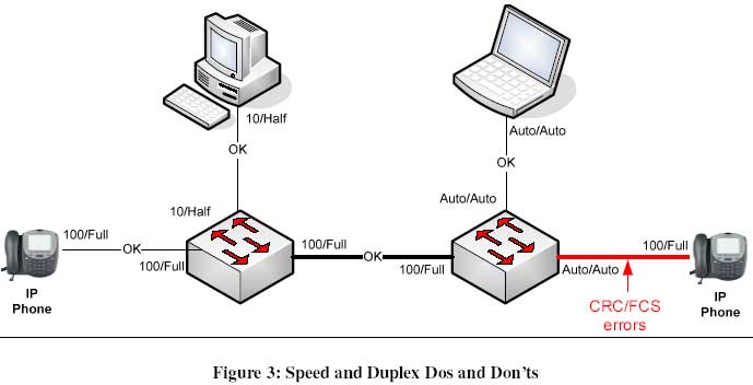
One of the most basic Layer 2 settings that cause trouble is the speed/duplex setting on a LAN switch ports. If speed/duplex settings are mismatched on a phone or IPT gateway and its upstream LAN switch, impairments like gaps in speech, one-way audio, and even resets may occur. Generally, if an interface can be hard-coded for speed and duplex, it should be. However, some older devices may not be hard-coded, and are only capable of auto-negotiation. In this case, corresponding LAN ports should not be hard-coded for speed/duplex, but instead left to auto-negotiate as well.
If access layer ports are to be used as either phone or data (or combined) ports, then the setting of the LAN switch port depends on the settings of the end devices that will connect. If PCs and phones are always set to 100/full, then locking the port to 100/full makes sense, but if the PCs and phones are set to auto/auto, then the LAN port should be left to auto/auto. The complexity is greater where mobile users plug in and where they may have access to change their own network interface card settings. If different IT organizations handle PCs, phones, and/or networks, there should be universal settings and standardized NIC and LAN port defaults.
Uplinks between LAN switches should not be overlooked. While most GbE ports are full-duplex by default and can't be changed, all 100 MBPS uplink interfaces should be set to 100/full on both ends of the wire. It is always a good practice to check the interface for Frame Checksum (FCS) and Cyclic Redundancy Clock (CRC) errors after connecting the device to the network. On occasion, some Linux and other machines may require some manipulation prior to properly settling down.
Figure 3 illustrates some correct and incorrect speed and duplex settings.
Spanning tree:
Spanning tree can be the culprit of one-way or total loss of audio when improperly configured. If spanning tree is being used to protect from bridging loops, the tree should be well documented to assure optimal traffic flows and to improve troubleshooting. Document the forwarding and blocking ports of the spanning tree topology for both standard and all of the possible failure conditions. Make sure that the optimal path through the network is provided during the standard condition, and make sure that the secondary path traverses as few hops as possible. If varying network uplink speeds are in place (i.e. 1G and 100M) to choose from, decisions should be made on how to manipulate the port costs, if necessary. If spanning tree is left to its standard blocking/listening/learning/forwarding algorithm, voice calls in progress will lose packets during the reconvergence period. A fast-start spanning tree algorithm should be applied to relevant interfaces in the network, like ports that service IP phones or telephony gateway/server cards, in order to speed up the time it takes for a port to begin forwarding when a topology change is detected. Testing the spanning tree in a lab to understand its behavior on IPT is recommended.
Virtual LANs:
VLANs offer many advantages for IP telephony, including improved security, QoS, manageability, and broadcast control. Media servers, gateways and phones should be placed in VLANs separate from data machines. Unless deployed in a very small network, IP phones and servers/gateways need not all be in the same VLAN. Typically, routing voice packets from a phone, through a router, to a server/gateway provides acceptable performance. If there are several adjuncts, like CTI, call recording, or voicemail servers, they can be placed in their own VLAN separate from the gateways and media servers, provided they are routable to devices/clients that need to access them.
It is a best practice to configure an 802.1Q trunk to allow PCs to plug into IP phones and share a LAN port, but still separate both into their own VLANs. When doing so, prune off the unnecessary VLANs from the trunk. Carrying extra VLANs can lead to problems if rogue traffic from an unknown VLAN is allowed to traverse the trunk. For instance, ports that interface IP phones should only allow the native data VLAN and the voice VLAN to traverse the link, not extra data VLANs that may be present on the switch. Note, that if a phone or other endpoint is tagging their frames with an 802.1Q header, and the LAN switch port is not configured as an 802.1Q trunk, the frames will be discarded by the ingress port. This would impact both signaling and bearer traffic, so is quickly noticeable.
Some have felt that VLANs are more trouble than their worth and have delayed adding an IPT VLAN at first, but have moved quickly to do so after experiencing voice troubles. It is true that in most networks, a majority of the time, a separate IPT VLAN is not necessary to provide better voice quality or stability. However, in the event of an anomaly, VLANs can provide better stability and help deliver the quality demanded by voice packets. For instance, in the case where a virus or broadcast repeatedly forces traffic onto a data VLAN, voice packets in their own VLAN would be sheltered and continue to flow untouched. Voice VLANs are like an inexpensive insurance policy, and as with life insurance, they're more effective when implemented early.
ATM:
While often forgotten in the IP telephony arena, some LANs and MANs continue to leverage ATM. When LANE is being used, proceed with extreme caution into IPT. In a LANE environment, there is no effective way to implement QoS. Once voice packets are converted to cells, they are no longer prioritized. Congestion in the ATM portion of the network could cause jitter or other voice impairments that Layer 3 QoS policies cannot affect. Additionally, with all of LANE' s logical functions embedded on different hardware components throughout the network, LANE has too many variables to reliably support IP telephony.
Of course, ATM is still a viable WAN transport. Optimally, Constant Bit Rate services are provisioned for Virtual Circuits carrying voice, but if carefully engineered, UBR can work. If UBR has to be used, bandwidth needs to be engineered conservatively and there should be no points within the ATM network at which congestion may occur at layer two. Take for example the topology in Figure 4, an example of what not to do. Even if Layer 3 engine in ATM 1 properly prioritizes voice over data on the way to ATM 3, since ATM 3 is unaware of any priority differences between traffic from ATM 1 and 2, data traffic from ATM 2 can keep voice traffic in the back of the outbound WAN queue. This is because upon exiting ATM 3, no QoS from Layer 3 is still applicable. In this example of both voice and data sent out a UBR virtual circuit, there will be congestion that delays and potentially drops voice frames. 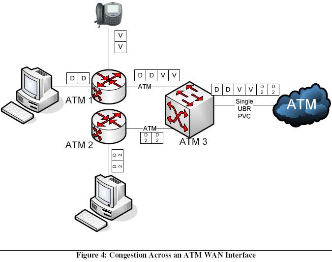
ATM' s cell size requires no major changes to IP telephony engineering principles like frame size (the frequency at which an IP telephony interface puts a frame on the wire). A standard 20ms frame fits into ATM' s 53B cell without additional wasted overhead.
MPLS:
Many enterprises are leveraging the any-to-any mesh capabilities of MPLS. MPLS can only impact IP telephony in positive ways, of which only a couple reasons are mentioned. First, most MPLS service providers provide options for sending different types of traffic into different prioritized virtual circuits. From the edge router, voice traffic is typically sent to a separate Label Switched Path, which is carefully engineered to provide low latency, jitter, and loss. Thus, MPLS provides an efficient way to blend voice and data on a single physical circuit. The only issue that some enterprises may have with current MPLS services is that they typically only provide one high-priority queue. For enterprises running voice, video, and streaming over the WAN, this presents a potential problem, since the carrier can't differentiate between the media flows. The MPLS network is not aware of the individual voice and video flows, it's only aware that there is more traffic coming in on a high-priority queue. In this rare case, oversubscription or Call Admission Control are two available solutions to maintain quality of service. Secondly, MPLS allows variance from the traditional hub-and-spoke model. This can benefit enterprises that want to have disjointed facilities communicate directly with one another, instead of hopping through a central data center. For instance, if a large marketing branch has a full contact center deployed, and a small marketing branch wants to tap into it, MPLS can directly connect the two remote sites instead of both coming through the hub. This simplifies bandwidth engineering and the challenge of enabling QoS throughout the data center core and multiple WAN links.
Quality of service:
Quality of Service (QoS) begins at the Layer 2 data link layer in the form of the IEEE standard, 802.1p/Q. Even if a LAN is equipped with 100Mbps to the desktop and Gigabit Ethernet uplinks, there is still a chance that voice packets could be queued behind data packets at some point. Therefore, enabling 802.1p is a prudent thing to do. Without enabling QoS end-to-end, it is very difficult to support reliably good audio. If there are voice quality issues, they' re often caused by congestion on the interfaces without QoS.
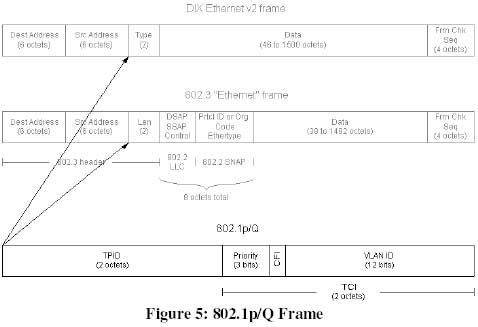
802.1p uses three bits within the 802.1Q header for setting the "User Priority" of the Ethernet frame. The resulting eight priority levels allow different types of traffic to be assigned to a different Class of Service (CoS). The classes are usually automatically mapped to different outbound queues on the switch ports that are configured for 802.1p/Q.
Depending on the switch, globally enabling QoS on the LAN switches often creates the queues by default, but it is usually required to manually configure the interface for 802.1p/Q. As a convenient coincidence, 802.1p/Q not only enables prioritized voice frames, but 802.1Q also allows an IP phone and a PC behind it to be in separate VLANs yet share the same wire to a LAN switch. The user priority bits within 802.1p allow voice frames to exit the LAN switch toward the phone before data frames are sent to the PC. Figure 5 illustrates the 802.1Q header, where it fits into two types of Ethernet frames, and where the user priority bits and VLAN ID reside within it.
Trust:
Some manufacturers' LAN switches either trust or re-mark the frames entering the switch interface. If the ingress interface doesn't trust the frame, it can re-mark the user priority bits based on something else in the frame. The re-marking decision may be based on the VLAN ID, the ingress port number, or if the LAN switch is Layer 3 aware, information in the IP header may be used to re-mark the Ethernet frame. Allowing the switch to trust ingress frames or packets reduces latency and processing power that would be required for the switch to inspect, remark, and then forward the frame. Trusting CoS is often preferred over trusting DiffServ Code Points (DSCP), since most network administrators are more concerned about users and applications tagging priority at layer three than at Layer 2. This is because some applications (i.e. softphones) are often preprogrammed to mark their frames with DSCP, but most applications are not able to control the 802.1p settings by default. Trusting CoS requires mapping Layer 2 values to Layer 3 values so that upstream routers are aware of the prioritized traffic. This subtle technique is discussed next.
QoS and the transition between Layer 2 and Layer 3:
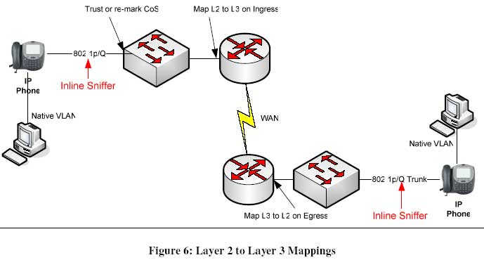
As a voice frame leaves an Ethernet segment into a router interface, the router can inspect the IP header for QoS information. Most phones and gateways can mark their IP packets with L3 QoS information, but the router may be programmed to not trust the IP marking (as described previously). If the router doesn't trust the L3 marking, the Layer 2 priority must be mapped to a Layer 3 priority within the router. If this isn't done, the voice packet may not be properly prioritized on the router's outbound interface or through downstream Layer 3 hops.
As a voice packet heads out of a router and onto an Ethernet segment, the router should be programmed to map the Layer 3 QoS setting into a Layer 2 Ethernet setting. This is especially important for voice packets coming from a remote site into a data center, where there are likely multiple Layer 2 hops prior to voice packets reaching their final destination. If voice frames are sent through multiple L2 hops without having the 802.1p bits set again, they'll apt to be congested in a LAN switch port on the way to their destination.
The default mapping behaviors of routers can lead to unexpected QoS markings, so researching and then manually setting the mapping is advised. The best way to validate that the QoS policy that you' ve designed is actually being carried out by the hardware is to put a protocol analyzer inline at both ends of the voice stream. Putting the sniffer inline allows you to see the Layer 2 VLAN tagging and QoS information. Figure 6 shows where the sniffers should go and where to apply the mappings discussed in this section.
About the author:
Christian Stegh is currently Avaya's IP Telephony Practice Leader for the North American Region. Among other responsibilities, he acts as a liaison between Avaya's customers/sales teams and Avaya's development teams, influencing direction of Avaya solutions based on customer input. Prior, he was a Managing Consultant within Avaya Global Services, designing, optimizing, and implementing hundreds of converged networks for customers. He began his IT career as a network engineer for a Fortune 200 manufacturing firm, where he managed worldwide L2/L3 networks. His interests not only include multimedia network performance, but also SIP, converged security, and business continuity. Feel free to provide your feedback to him.